Monday, February 18, 2013

Wingbar corners & foil strut - Part 5

Two of the more complicated components were always going to be the bladder moulded wingbar corners and the centreboard strut. I put off starting them for as long as I could, but at some point I needed them to progress so I had a coffee and started working out what to do.

I did a bit of research on the web on bladder moulds, and found this guy to be quite helpful. Im sure there are other similar vids but by the time you've watched those, you'll probably have gained all you can and then you have to do an experiment. I had two tests with cheaper materials before biting the bullet and laying up the first part. The first test was pretty hopeless, but by the third attempt I had it down.

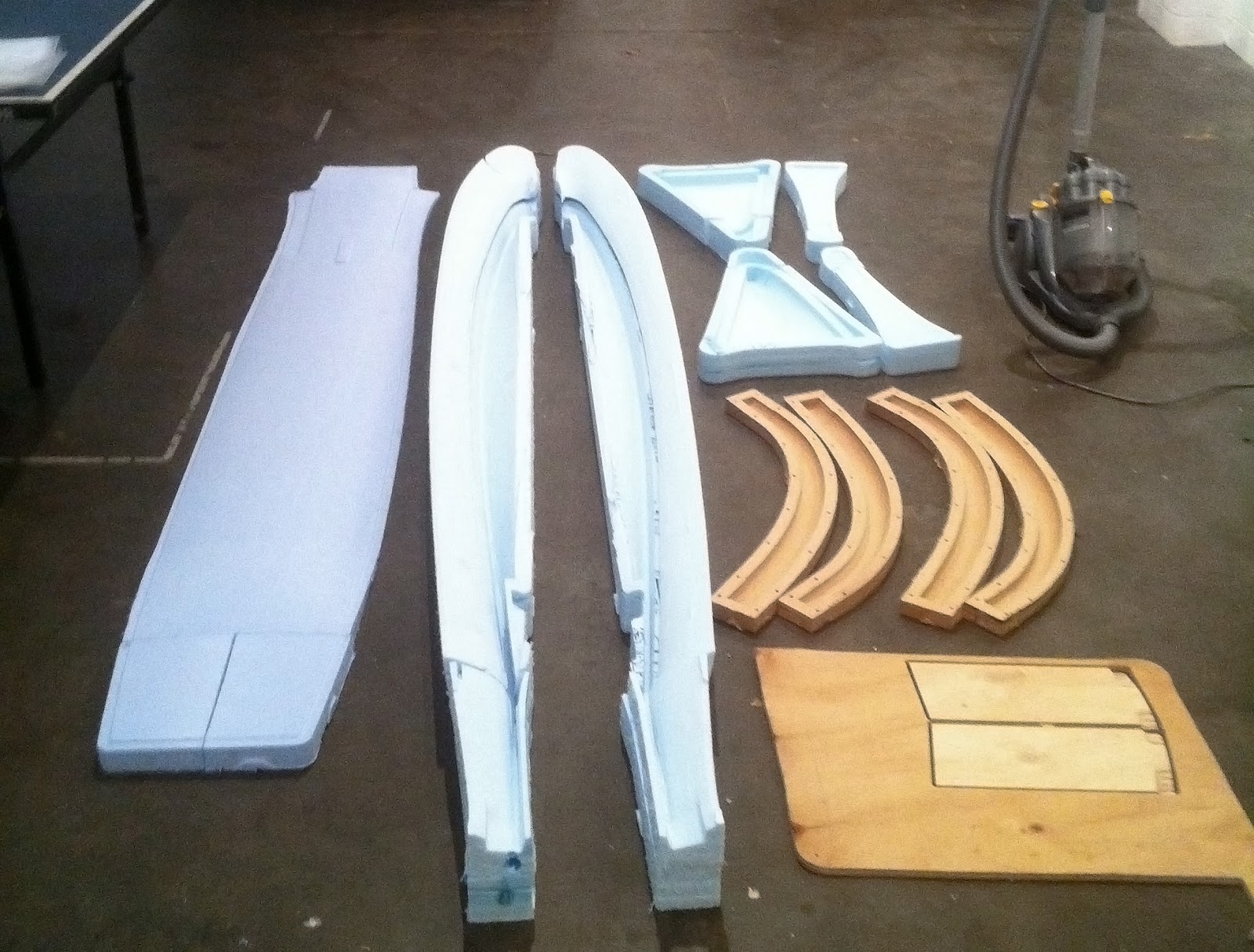
 The moulds I had finished and prepped earlier, and worked pretty well but in hindsight they could have been stronger to take the fairly serious pressure that they get put under. On one, the MDF split at the join where the two thicknesses of wood had been laminated together, and created a bit of a bump in the finished part. MDF is ok, but probably use a single thickness or glue the sheets together with something better than PVA!

I made bladders as shown in the video, with a soldering iron ground flat at the tip. I went through half a dozen before I got one that would go the distance. I used black builder's plastic, but something more elastic would have given a bit of margin for error - it was too thick and would split before it would stretch. Making it quite oversize seemed to help, with the final size being almost twice the circumference and 100mm longer than the mould. I used a barbed Nitto fitting that plugged straight into the compresser and sealed it to the bladder with a big rubber band as in the vid. A bit of plumbers tape helped, tacky tape was surprisingly useless under positive pressure.

I laid up the tubes so that the carbon in one half was about flush with the seam, and the other half had a 10mm overlap on both sides. That seemed to make it easier to get the bladder in - deflated with the vacuum pump - and then get the carbon to seat cleanly onto the other half when closing the mould. Once closed, I found it could take 40psi without too much drama, and I just left it like that until it cured. Sometimes there would be a slow leak, and the compresser would just cycle as required. That's not ideal, and it's worth getting a good seal.

It's surprising how much more compact the laminate is when cured at 40psi (2.75 atmospheres) compared to under vacuum. The corners came out at about 460g each, but considering how much carbon was in them, that translated to a resin ratio of about 30 - 35% which was on the money I reckon. They are about as bullet proof as I could hope to build. It's a great process.

The two test runs and the finished product

Making the plastic bladder with the soldering iron, baking paper and template

The two halves pre-bladder

The bladder deflated and held in a bundle with blu-tac. With such a thick laminate it was quite difficult to get it to all sit down long enough to close the mould.

The mould closed and under pressure, with resin oozing out of it

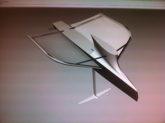
The centreboard was fairly straightforward by comparison, the only difficulties being the meaty layup and the carbon pultrusion that needed to go down the middle. I used standard modulus carbon even though there was some IM available from CG, only because I already had it lying around. I reasoned that the foil section is quite thick at the hull intersection, and that it should be inherently quite stiff, but at the end of the day you can't go wrong with higher modulus material. Next time.

When laying up, I added some extra laminates to build up a flat section for the pultrusion to seat onto. That was all bagged down and in a second step I closed the mould with glue and foaming epoxy inside and let the excess foam spew out a couple of holes. The idea was that as the foam expanded, it pressed the glue into the joints. It seems to have worked, though it's a bit heavier than it could have been - at 250kg/m3 fully expanded, the foaming epoxy isn't as light as a milled foam core, but it is convenient. The whole thing went into the oven for a ~12 hour post cure.


Making the cutting template from aluminium foil

Cutting out the carbon 


Under Vacuum


Monday, February 11, 2013

CAD to real life - Part 4

The build is progressing well, an I apologise for getting behind on the blog, but I thought it might be neat to sum up some of the tricks I've been playing with in an attempt to keep the project on schedule. With a detailed Rhino model as a reference, it's been amazingly efficient to print or CNC cut templates for all sorts of jobs at 1:1, eliminating the need for double-handling of measurements and reducing the potential for certainty of operator error. If only you could make buildings this way, it would save all that time making 2d drawings from the 3d model, only to have them poorly re-interpreted back into a 3d building! Here we go from 3D model to 3D boat.

For a start, it has been fortunate that the Alpha hull is incredibly close to the original digital shape. John Gilmour did a nice job with the mould, and I guess would have used CNC to cut out the stations from his initial model. I'm benefiting from his hard work now, with the female moulded deck, foredeck and wing fairings mating onto it with only minor swearing and banging.

All the internal bulkheads were hand cut from carbon flat panel, guided by templates that I created in rhino using the 'section' command. I made an allowance in the drawing for the thickness of the shell, and just followed the line with the jigsaw. They all fitted perfectly first go after an  hour's work, a big time saver compared to the last boat.

To align the wingbars, a traditionally painful job, I cut a couple of templates from some scrap MDF on the CNC. They eliminated all the guess work in setting up the wings, it was almost too easy. You can see how perfectly the template mated to the CNC cut deck. In the end though when I eyeballed the wings, I decided that they needed to be a bit steeper, so I propped up the templates off the deck a bit to get that to work.  I guess it's always a bit of a surprise when you see the real thing having 'understood' it on the screen, and you have to trust that you can make judgements in real life too. I had to then adjust the CAD model to reflect those changes so that the tramps would still fit!

Another job that was painful last time was doing all the tube copings. There are coping calculators around that would have helped me before with the round tubes, but with a few foil sections in the mix, that becomes a bit problematic as well. The solution was to model the exact sections in Rhino, intersect them and the use the 'smash' command to unwrap the surface into a flat piece. Then you have a template that you can just print out, wrap around the tube and cut.

A few assorted pics below:


Tuesday, January 29, 2013

Deck and fairings

With the foam moulds finished for the main hull components, it was time to do the layups and pull parts off. I did the smallest part, the foredeck first to test the process using a few odd-shaped bits of carbon and some 3mm Nomex inside the curved section.  It was a bit of a half-assed job and when it came out, it was a little bit heavier than I'd hoped - just under 500g - but in the end I decided it was god enough to use. I did the deck and fairings next, one at a time as the vacuum pump was sounding a bit sick and I didn't want to loose them all at once. Meanwhile I made an effort to track down someone who sold vacuum pump oil. 

The fairings were simple to lay up except for the sail track that picks up the lower skin of the tramp. That ended up being a 9mm ID tube that I glued into the monolithic carbon part, and then reinforced a bit more on the inside and cut the groove at the end. 

The foredeck fresh out of the mould

The deck was the last thing to do, and I laid it up with 200g cloth on 6mm foam with some local reinforcing. On Andrew's (CG) advice I used a bit of 75g glass between the foam and the top skin of carbon to trap some extra resin there and ensure a solid bond, as I had some delanination there with my last deck. I carefully cut the recesses for the wingbar sockets out of the foam, not realising they were the wrong way around, an went ahead with the layup and the bag. It all sucked down very well when the vac pump finally choked and died. I think some oil leaked through the shaft seal and into the motor, and started burning on some hot part. I turned off the valve to seal the bag and just waited to see if it was all going to go to waste. Amazingly, the bag and foam mould were completely sealed, and it held a reasonable vacuum until cured. I ended up with a bit more resin in there than I hoped, but the part was usable. If I did it again I could probably save 50-100g, so a bit like the foredeck, I figure I can live with it.

I went to the cleverly named vacuum pump place 'absolute vacuum' and sorted out some new oil, took the pump apart and cleaned it out, and miraculously it now works like new. It turns out when you let it suck resin and whatever else into the rotor, it stops working. I now have a proper gauge, but am still waiting on a couple of valves and a new 'catch pot' for all the unwanted bits, and then I'll have confidence in the pump again.

the deck gallantly holding a vacuum
Laying up the carbon tube for the sail track. The mandrel was a bit of clear hose
fed over an old yacht sidestay. Because the hose getts thinner when you stretch it,
you can just pull it out.  It worked really well.
The back of the sail track, showing the bit of reinforcing on the inside.

Anyway those four major parts are now ticked off. The deck weighed in at 1.6kg with the fibreglass rods glued into the sides, the fairings / sail tracks ended up being a bit under 1.4kg for the pair. That's a bit of a weight penalty, but it's a trade off - add a bit of weight, subtract a bit of drag. It's hard to know where to go on things like that, but I'm committed to the design so im going with it. I can always cut them off again if the boat's slow. 

The last image is of the four parts post-curing on the roof. It was easily 50 degrees up there so I thought why bother with the oven!


Wednesday, January 23, 2013

Part 2 - tooling up

I was thinking of calling this port 'tooling around' because that probably best sums up what I've been doing for the last month. No-one cares about that though, instead Im going to run through the process for creating all the moulds needed for the new build.

Because I still have access to the CNC router - its now being housed by my mates at Street&Garden Furniture Co. - it was pretty straightforward to send every part, big or small, to it and create a set of female moulds. Detailed things were made in ply or MDF, and the large simple shapes were cut from 'Isoboard' EPS insulation foam, recommended by the guys at CG. I designed the boat and made the 3D model so that everything would be able to be done this way, and it was super quick to pull parts out, create the toolpath and press print. I set up a new dust extraction system to deal with the polystyrene dust, and it works really well. didn't miss a drop.

Here's a photo of the setup, and another after a weekend's of successful routing.


The bigger parts took an hour or two to cut, the smaller ones obviously were quicker. I had a couple of small issues cutting the foam where it melted etc, but that's boring so I won't go into it. Thick parts were made in layers 75mm thick, and then guled together with epoxy later. The rough-ish surface (3mm step) sanded back easily and I then sealed it with some epoxy and colloidal silica bog. Then another quick sand, another layer of thinner epoxy/silica, carefully applied with a credit card, and you're done! The moulds all held a good vacuum with no problems, important because you can't envelope bag it as it compresses the foam, and the surface quality was generally within range of 'high build'. It's gotta be the quickest way to make large composite parts.


The MDF/ply bits are now pretty straight forward. I've learnt that it's better to cut them with a much finer stepover (1.2mm or so) so that you almost don't need to sand them. It takes a bit longer on the machine, but saves you lots of stuffing around later. Then one coat of resin and a sand and they're good to go. The foil strut mould was the last thing I did, and turned out the best.

Saturday, January 19, 2013

The build - part 1

Just reporting that construction is well under way on the new boat. After reading Phil's post the other day about how the moth blogs are drying up, I thought I might as well have a crack at keeping this one a little bit up to date. Uncharacteristically for me, the build is well ahead of the blog, so this and the next few posts are going to be something of a retrospective about the various stages of the construction that began in December last year. I've tried out a few interesting methods that I'd like to share, that have really sped up the process and allowed for a bit of extra complexity.

So, this is what it's going to look like:


The design is based on the shapes I was playing with in the last post and prior. The design development/evaluation did progress to a better CFD package (thankfully), and the results looked promising enough to invest some time in building. You have to draw the line somewhere right? There was certainly still room for improvement but CFD runs take so much time that I got sick of trying new things and decided to aim for some real world testing. More fun. Notable features: wing shaped tramps blended into the hull for super sweet aero, forward mast and foil position, centre 'console' to consolidate all the messy lines and reduce drag, aero gantry and probably some other things that I'm not talking about just yet. The rig, mainfoil horizontal, complete rudder and adjustable wand are all spares that didn't go with 'Half Meanie'.

As usual my composite products and consumables have come from CG composites, Tubes are from CST, and the tramps will be built by Yancy and Pete Williamson at Doyle Mooloolaba. Thanks to all those guys, I appreciate their patience and technical know-how. The hull shell was built by Doink, and mate once I got all that furry shit out it looks great, cheers! Very light and stiff in pre-preg from John Gilmore's Alpha mould. All the little fiddly bits will be 3D printed from Shapeways where required -easier and cheaper than machining. Sometimes.

Current status: All the large parts are done, internal structure is half-in and the wings are about to go together. Here's a photo taken a couple of weeks ago of the whole deal held together with sticky tape. Target finished hull weight is less than 10kg.


Tuesday, January 24, 2012

entry level CFD

CFD has been - and probably still is - the realm of people who know what they're doing. However recently Autodesk released a little bit of software called Vasari, which is really a software preview of some of the things that might be available in future versions of Revit. The 'wind tunnel' in Vasari is admittedly a bit crude compared to other things on the market, so you have to take the results with a grain of salt, but it does seem to give a reasonable impression of what goes on.

The thing I have been initially trying to test for ís whether the hull tramps in any particular configuration acts as sail, or otherwise increases the efficiency of the sail. This could probably come about in a couple of ways:

  • The wing tramps act as an end plate, and reduce the size of the vortex coming off / wrapping around the boom
  • The leeward tramp generates lift in a downward and to windward direction when the boat is heeled strongly to windward, acting as not very productive sail
  • A fixed foredeck fairing of whatever size could generate lift as long as the AOA is reduced somehow so it doesn't stall, or it is a very high stall angle section
  • A fixed fairing might fill the gap between the deck and the boom and increase the end plate effect, even if it is stalled.
  • The underwater profile of the hull generates lift

There has been mention on Facebook that there might be some legality issues with fixed aerodynamic fairings attached to the hull. I couldn't immediately see where aerodynamic fairings of this sort were ruled out, but please if you want to comment do so, I want to open up the discussion.

a couple of screen vids showing the airflow over different tramps, all other things remaining equal:


An early hypothesis is that the vortex trailing off the tramp actually seems to counteract the one from the bottom of the sail slightly. When you have a full tramp, that vortex seems to work better than with a small tramp. Just an early theory though.


gh

For those who aren't all over it yet, grasshopper is a plugin for Rhino that allows you to build 3d models parametrically. You can choose to model the normal way and just let grasshopper calculate the surfaces, or draw every component from scratch in grasshopper. By using number sliders for certain dimensions, you can create fully adjustable 3d models that you can easily change and optimize after finishing the model.

In my experience this type of modelling is normally used to make things like this:


But that said, I know people use tools like Catia and Generative Components in all sorts of industrial and product design fields. So parametric models are probably being used to make boats. In fact, I'd say that if you are trying to design a boat and not using a generative 3d model, then you're doing it tough.

Here's a screen vid of one of first forays into moth design using grasshopper - the parametric wing: Apologies for the daggy commentary and vigorous cursor gestures!

Friday, November 4, 2011

back on the horse

Its been about 10 months since the worlds. A pretty good amount of time to rest, digest new information, work on other things etc etc. But, the itch to go sailing is back and I now have a Doink-built Alpha shell (thanks mate!) sitting in the garage waiting to get turned into a new boat.

So, the plan was to start with the most outrageous contraption possible, and gradually change it into something that sort of worked. I'm not sure about that plan anymore, due to day to day time constraints and the pressures of modern life and whatever else. So, I've decided to go with something more conventional. Evolutionary rather than revolutionary, and maybe then try and put a wing on it.

But, it seems like a waste to just chuck ideas away, so I decided to post some things I've been thinking about on here, maybe generate a bit of discussion and possibly inspire someone else to take it a step or two further. They might trickle in, but here's the first one.

The canting foil.
After an initial thought experiment and then some basic 2d cad "calculations," I decided that this would probably be worth a try. But a discussing it with Nick and Markla, we came to the conclusion that it was going to be a lot of work and structural compromise for no a huge gain. Markla did a few proper numbers to illustrate this point. Anyway, I'm still not completely discouraged and it will just go on the back burner I think!

The system I arrived at to make this work is as follows: The foil cants side to side about a bearing mounted at deck level. Very important to have the bearing on the deck, as you seem to get absolutely no advantage over a fixed foil with it at the keel. The bearing needs to be pretty snug, so there are replaceable nylon inserts inside the carbon tube. The centreboard case is supported from the top, but a sliding 'car' that runs along a bit of aluminium bike rim acts as a third point in case you hit a sand bank. I was initially thinking of using a stainless lead screw to control the cant, but decided there was too much machining involved, so I went for an 8:1 purchase system running through laminated-in thimbles. The purchase would need a serious amount of pre-tension in the form of a big bungee to compensate for the changes in line length between 'centred' and 'canted'. Even so, you would never achieve the stiffness from the foil that you get from a fixed centreboard case. That's probably the biggest trade-off. Another issue is that you're left with a large hole in the bottom of the boat, which is among other things a structural problem. This is overcome by some longditudinal bulkheads that tie the fore and aft bearings into the chines and act as beams to stop the hull from snapping. A laterally sliding carbon plate, flexible in one direction only, sits around the base of the foil and fits into a specially moulded carbon groove at the front and back of the hole (not modeled, quite difficult to draw actually) and a small fixed venturi drains it.

In the end, the foil can cant through about 15 degrees comfortably, which is all you would need. From a sailing point of view, i envisaged that the controls would be quite lightly loaded and accurately adjustable. You would probably just centre it in the tacks and when sailing downwind. its an upwind device really.


Wednesday, February 16, 2011

interview


Finally got around to watching my interview from the worlds. Knowing full well that i'm a pretty rough looking bloke I was putting off watching at it in the name of self esteem, but now I've seen it and i think the worlds media team really did a great job so i thought I should share it. The particular 'some guy' mentioned I think was Bill Olsen (with probably the nicest paint in the fleet) - don't think we'd met at that stage.
cheers

Sunday, January 23, 2011

Belmont


thanks very much to Thierry Martinez for the shot. www.thmartinez.com


Without going into too much detail, I had a great time at Belmont. It was especially good to meet so many moth people for the first time. Thanks to John Harris and Clive Watts for helping me get set up with a rig that worked, and cheers to the guys like Andrew Stevo, Bruce Gault, Bill Olsen and Al Goddard who generally hung around the repair shed and were really generous with their advice and bits of carbon. It was also cool to meet Dave Lister and check out some of his genius carbon work on the 'monstro' and likewise Luka with the scalpel and John Ilett with his latest prowler. All three are lovely looking boats with great ideas and top blokes behind them.

So anyway I didnt do very well on paper - 34th in the silver fleet and I think over the regatta i had as many DNFs and i had places. In one race i did manage a 15th in silver, which I was quite happy about in breeze. Also i logged a new top speed on the speed puck of 27.2 knots. I was really pleased, but I heard later that the fast guys average that on a downwind, so again i need to find another gear.

The boat performed reasonably. I cant say I had it right on its game because I was stuffing around with the foil angle of attack the whole regatta, and never quite got it right. I noticed after the first day's racing that my boat was sailing around with the flap fully down, which cant be fast. The refinement process was complicated when I snapped the strut in one very windy race, after the gudgeons on the gantry came apart and the rudder parted company. I could say I was a victim of the weed clumps, but the reality is that I needed a carbon spar in the strut. On Bruce's advice I hollowed it all out and glued a stack of carbon rods in the break, then scarfed the laminate back over it and she's probably stronger and stiffer now than before.

for reference, A good angle of attack for my main foil design is 2.0 - 2.5 degrees from what I have seen and what people suggest.

I got more DNFs for other stupid things - my vang strop came undone at one point and I had to sail in to fix it. The sail got chafed on the concrete and wore through the webbing strap at the top, causing it to fall down the mast and I lost 3 races I think. Angus had a similar issue and we were both at the sailmakers on the same day. Probably the dumbest was when I went out after racing was cancelled in a gusty 25 - 30knots, and blew up the vang, causing the sidestay to get overloaded and rip the front wingbar off the boat. the rescue was a bit difficult and I felt a bit bad for going out and causing drama when I should have stayed on shore. the wingbar will be sleeved together in good time, but after that I called it a regatta. It was actually pretty fun sitting in the club on the last day watching the racing. probably the best spectator sailing ive ever seen - and ive watched a lot of match and team racing!

So as a way of capping off this post, heres a diagram of something I was keeping a bit secret. Its my integrated hinge concept. It has never worked in the past, but I fixed it I think. It survived the nationals and worlds anyway. The trick is to make the centre 70mm or so a standard sikaflex hinge like a bladerider, and then have a couple of narrow points, about 5mm wide (section a) along the span to stop the hinge going 's shaped'. section b shows the normal 10mm gap to allow the carbon surface to bend around a decent radius. A few people mentioned that it might work better if the seamless surface was on the bottom, which is fine, as long as you keep the hinge dead straight so it wont bind up.


Friday, December 3, 2010

foil progress

finally had some racing this week. I've been waiting to see if there was some video that I could scavenge from the pretty decent Sail Brisbane media coverage, but despite having a camera gaffa-taped to my boat I don't feature anywhere except for some brief moments. Always a bit apprehensive watching videos of yourself - its hard to know whether you're going to look like an uncoordinated fool or not. i reckon a bit of column A and a bit of B.

Aside, the foils are going well and both the boat and my technique are improving. Had a top speed of 22.7 in a predominately light to moderate-air and choppy regatta. Still that's the fastest the boat has gone, although I reckon there's a lot left in it. I never really felt like i had it wound up. Anyway hopefully with a new rig and some tweaks here and there I should get away without too much embarrassment at Belmont.

Still cant get the height control perfect through the chop, although i was pleased to see everyone else having occasional problems as well! People keep telling my that my boat goes up and down more than the others, and I'm not entirely sure what to put this down to. Sure the waves are a factor, by why do the affect me more than others? I'm putting a kink and my wand to try and space it further forward of the foil and we'll see what that does. I know the bowsprit is an option but i quite like the bow as it is. Also a lower profile boom will allow the mast to come back further while still giving me enough space to get through the tacks. more rake may help.

I put limiters on the flap down and flap up because I found that too much movement was causing a bit of cavitation around the flap that I could actually hear from on the boat. I suggest to anyone looking at building the foils that they do this too. Mainly down- 15 degrees is too much deflection. I'm not sure what its set at now, but email me if you're interested and ill measure it.

Also worthy of note, the ride height lever was really helping my takeoff. I worked out that i can neutralise the flap, reach off and get the boat speed and apparent wind up then gradually pull the ride height on, and the boat takes off much more easily than it otherwise would have. at the risk of losing what may be a slight edge, i reckon the same technique will work with a dial on your mach 2, prowler assassin or whatever you happen to bring to the potentially marginal foiling conditions at the worlds.

a couple of photos courtesy of the AYF media people, (http://www.saildownunder.org.au/) who by the way were tops.


So, reckon I should try and paint the boat before the worlds or is it fine as it is? I'm tending toward no, but I could be swayed. I think the rust stains particularly add charm.

Sunday, October 24, 2010

simple harmonic motion

so no results from the foil testing as yet because i cracked the bottom rudder gudgeon before the first race. sometimes when you say 'that probably wont be strong enough' its a bad idea to convince yourself that it will be. anyway its glued back together and tomorrow it will be beefed up and i should make it on the water later in the week.

The reason I loaded up the rudder and snapped the gudgeon was because of the annoying downwind motion the boat exhibits through our short chop. I drew a diagram to help myself understand what was going on- my theory is that the wave motion is wildly changing the angle of attack on the foil as it goes through the water. This can be up to around + - 5 degrees or more, depending on the boat speed and ride height. The boat tries to follow the wave- up the back and down the face - but there is a bit of lag because of Newton. The flap also complicates things a bit because it is reacting to the lag and not the wave.

The calcs suggest the best thing to do is go faster. The more waves per minute you go through, the less time F=ma has to crash the boat. But the faster you go, the greater the lift from that extra AOA and F becomes a bit more significant. also, there will be a sort of no go zone, where dead square is ok, beam reach is ok, and somewhere in between the effective wavelength gets in a problematic range and causes this kind of crap behavior. Probably people who can sail will be saying 'duh' but this has been hurting me for ages!

I still don't get why 2 boats with very similar setups will respond differently to this. Ncik said its all in the shock chord...

PDF here

Friday, October 22, 2010

more tinkering less sailing

I think the 'hours tinkering to hours sailing ratio' this year is about 278:6. Not doing my boat-handling any good at all. I've been thinking i should really just outsource the sailing part and focus all my energy on stuffing around in the shed. Anyway although I'm still not landing most of my maneuvers, my work with CNC and carbon is getting better and I've been busy applying the stuf I learnt building the moth to other products.

Anyway here are a few pics of my (almost) finished set of foils. They've been out a few times now and i think they could be on the pace. not that I can judge, of course, because no-one ever comes sailing with me! Thats probably my fault for having the boat in bits every time theres a race on and going out mainly on Tuesday mornings.. mm. The 3D model of the foils is available for download permanently on the right hand side of the page. Ill get back on here with an actual review when I've had a chance to line up against someone.


The top of this has become a bit of a mess. It functions, without any reference to form whatsoever. I like it.


I also chucked a set of spreaders together. So far they work. And they weighed in 300g lighter than my old ones.
Finally, has anyone got a carbon boom they want to sell? My alloy boom is nearly dead, (ugh, corrosion) and probably adds about a kilo or more onto the boat! Luka mentioned there may be Mach 2 owners who have upgraded to CST HM gear and have no use for their flexy Mach 2 boom. Anyway I reckon even the worst carbon boom will vastly improve my boat, so please let me know if you know of anything.

Right, now for some sailing.